Getting Terminal Access to a Cisco Linksys E-1000
Over the past couple weeks, I’ve been spending a lot of time hacking on various embedded devices to figure out how they work and perhaps identify a couple vulnerabilities in the process. One of the fun parts about this experimentation has been exploring how to get terminal access to these devices, seeing what type of software they are running and interacting directly with the underlying operating system. Once you have access to the operating system via the terminal, most of the same techniques for vulnerability assessment still apply.
I recently read an article on the /DEV/TTYS0 blog about reversing serial ports and found the process described there to be very practical for getting terminal access to a variety of different devices. Today I’ll be sharing my recent experience of getting terminal access to the Cisco Linksys E-1000 platform, one of the more popular home routers in use today, and the process I took to get terminal access to the device. I won’t be talking about any vulnerabilities in this platform, but I’m hoping that in the not too distant future, myself or one of my team members will be able to share some of our findings on devices in this space once the necessary vendors have been notified and patched accordingly.
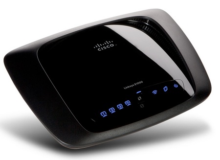
Before we get started, it is really important to point out that the process described below can easily be translated beyond just home routers and the Cisco Linksys E-1000 platform. In fact, many devices in your home or even on your person include similar interfaces, which allow you to obtain terminal access to assess the security of these platforms. Some other example hardware platforms that fall into this category include iPhones, Androids, Arduinos, MiFis, IP Cameras, Video Cameras, RaspberryPi and many other others.
Getting Access to the Circuit Board
When attempting to get terminal access on an embedded device like a home router, the interfaces that you will often need access to will not be directly accessible. This means that you’re going to need to open the outer shell of the device and interface directly with the circuit board. This also inherently means that you’re likely going to void the warranty on the device, which should be considered carefully if the device is expensive and you still have a service contract. As for small home routers, they are relatively cheap and in the rare case that you manage to “brick” it, you’re only out about $20 USD or so.
When trying to remove the outer shell from an embedded device you’ll want to give the device a good look over and understand how it’s being held together. Most of the time, this process includes removing a handful of screws and then splitting the device open. If you cannot find any screws on the device, it’s possible that they’ve been concealed under the rubber pads on the bottom of the device. These rubber pads can easily be lifted up with a small screwdriver.
In the case of the E-1000, which I haven’t seen on many others, security screws were used to hold the device together. Security screws are simply non-standard screw heads that will prevent the casual consumer from opening the device. Here is a look at the security screws on the E-1000 along with a better picture of what the head looks like.


The bits that drive these types of security pins are much less popular than say a Phillips or other bit sets. However, you can still buy them at a specialty electronics store or Amazon for less than $5. Here is a look at the bits that I purchased at a local electronics store.
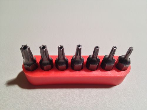
After removing the security screws from the E-1000, it did require a little force to remove the cover fully. This is a common occurrence with devices in this class in that they usually have additional plastic snaps or clips that hold them together. If you are removing a cover for the first time, it will likely require some force, but be careful not to pull too hard and break important bits on the device.
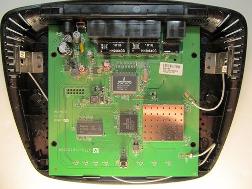
Here is a look is what the inside of the E-1000 looks like once you’ve got the cover removed:
Identifying Interfaces
On embedded platforms, you are likely to find two common interfaces that can be used; JTAG and Serial. JTAG is a very powerful interface and allows you to do really low-level tasks on the device including programming the chips on the board, inspecting memory and variety of other privileged tasks. Serial, relative to JTAG, is a very simple interface, but if you’re looking to get terminal access to a device, the serial interface is what you are looking for.
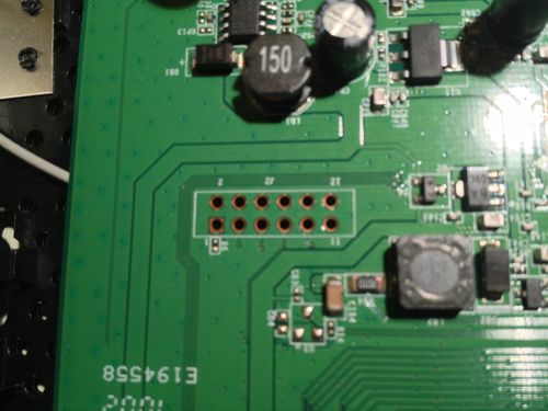
In many cases you can quickly identify the JTAG interface by its form factor, which is typically a double row of pins or unused sockets on the board. Often times, vendors will not solder pins into the JTAG slots because they are typically only used during product development and there is a cost benefit in not having to install them for each consumer device.
On the E-1000, the JTAG pins are left empty, like so:
Finding the serial interface on the E-1000 was a little more challenging, which made it more interesting. The other devices we explored recently all had either an empty socket or a soldered pin set that you can tie into directly. For the E-1000, the serial interface consisted of 5 test points (TP12 – T16) on the circuit board.
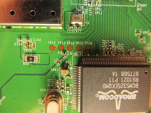
The /dev/ttys0 blog post I noted above was very helpful in identifying ground, receive and transmit pins that made up the serial interface. The challenge with having flat test points directly on the board is that it makes it more difficult to connect a wire to the device and reliably talk to its serial interface.
As a solution to this problem, we took a really fine tipped soldering iron and placed solder balls down on each test point. Each test point was then wired using 30 AWG wire to a custom pin set that was fashioned from a spare electronics board and then hot glued to the E-1000 circuit board. Here is a look at some of the modifications that were made to the board.
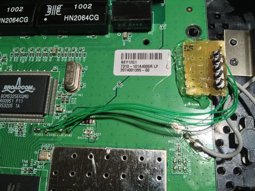
In many cases these modifications will not be required, but in other cases it may be one of the only ways to obtain a stable connectivity point to the serial interface.
Identifying Serial Voltages
Once reliable connectivity points are established to the serial interface, the next step is to figure out what voltage the serial interface is using. With the addition of these pins, it makes the process quite trivial with a couple hook cables and a multi-meter.
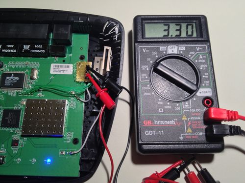
Like seen above, many of these devices will use 3.3v for serial communication. In limited testing, nearly every model tested used 3.3.v for it’s serial voltage. This matters because you don’t want to use a 5v cable on a 3.3v device. When you mismatch the voltage on a serial interface the best-case scenario is that you won’t be able talk to the device. In the worst-case scenario, you could actually damage components on the board and end up “bricking” the device, which means you’re going to have a bad time.
USB to Serial cables can be purchased from a number of sources, including Amazon, in both 5v and 3.3v. If you do end up buying one, I would highly recommend getting one with the FTDI FT232QR chipset, which has support for most operating systems, including Windows, Linux and Mac.
Getting Communication Working
Once you’ve got your new shiny USB to serial cable, the next step is to connect everything together. I prefer using breadboard M-F jumper wires, which are great for prototyping. You’ll want to slide the female end over the pin sets that were either on the board or that you created yourself and then put the male end into the connector on the serial end of the USB to serial cable. You will then want to plug the USB end into your computer to complete the hardware setup.
After getting everything plugged in, the next piece is installing the drivers and figuring out what the name of your new device is called. On Windows, you can learn the device name by visiting device manager and on Linux and Mac you can simply list the files within /dev and look for something with usb or serial in the name until you find the right one. (Example: ls /dev/usb*)
Once you’ve determined the device name, the next step is determining the baudrate settings. Many of these device types operate at 115200 8-N-1, but not all of them. In order to figure out the baudrate settings of a device you can either try to look it up from the manufacturer spec sheet or take a brute force approach and start guessing the limited number of commonly used settings. Keep in mind that brute forcing the baudrate setting is a pretty easy and fast way to determine the what’s required to talk to the device.
The last part is firing up your favorite terminal emulation tool, like Putty, Screen, Minicom, etc. and talking to the terminal directly. Here is a screenshot of talking to the E-1000 via it’s terminal interface as it boots:
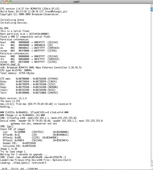
Now that you have access to the internal OS for the target device, you can explore the operating system much like as if you sitting at the console of any other system. This also means that if you’re hunting for bugs in products of this style, you have much more detailed information about what’s going on behind the scenes. In the case of the Cisco Linksys E-1000, it was running BusyBox, which is pretty common for devices in this class, but you can still navigate around in the operating system and learn more about how it works. Another interesting tid-bit about this device was that whenever a configuration change was made, it was echo’d as a debug message onto the serial interface allowing a much richer feedback loop for further vulnerability analysis.
Video Demonstration
In my opinion, the best way to understand something new, especially when it comes to hardware, is to have someone show me in person. Since I can’t be there to show you all in person, I’ve put together a little video to demonstrate the above described process from my point of view. Please note that this is my first time using iMovie and my mom says I have awesome taste in music, so please be gentle.
Also, if you’re interested in the Ruby-based serial tools I showed in this video, I’ve decided to open source them here so you can have fun with them too. If you have other ideas on how to improve the tools or techniques I’ve shown for evaluating serial interfaces on embedded devices, please send me a note or a pull request.
PS - I want specifically thank Craig for his work over at the /dev/ttys0 blog which acted as an excellent resource of information as I was working with and learning about various embedded devices over the past couple weeks.
